

: Key trends and technologies shaping the future of customer interaction")


Before a designer can bring his design to life, the sketch of the model needs to be prepared in any of the CAD/CAM software. In many cases, the predominant step for CNC milling is the CAD model in software like Solidworks, CATIA, PTC Creo, and many other GUIs available on the market. CAM software is used for opting tools and simulating the tool path through milling.
CAM software needs DXF or DWG formats of the CAD model. CAM creates a program file, which contains G-codes readable by CNC milling machines. Few techniques will need to be implemented for the best result.
- While designing CAD models for CNC milling, restrictions like natural mechanics of the cutting process, tooltip, tools axis, and machine axis scope, work-piece stiffness, tool stiffness, and work holding need to be considered.
- The height to width ratio must be less than 4 (L/W < 4) because tall features are more exposed to vibration and may cause an accident, tool, or model damage.
- Milling parts on both sides (top and bottom) features meeting at some wall distance from both sides; if it remains thin during the machine, the wall may damage. So, that thickness needs to be considered while preparing the CAD model.
- Reduce CAD model into a single layer, clearing up CAD model by eliminating redundancies like construction surfaces, lines, etc.
- Define tolerances in the process of CAD modeling. In case of failure, 0.125mm default value be considered by CAM software.
- If internal corners are needed at a right angle, space for T-bone tool access must be designed in the CAD model.
- The text projected on the design must have a spacing of at least 0.5mm.
- Delete any duplicate copies of the objects, fuse all the lines that overlap, and combine different sections as a single entity.
- Chamfering/filleting of external corners can be avoided if not required for better lead-time.
- In the case of reverse engineering, a picture of the complex part may be taken, and importing it to any CAD software and tracing it will minimize the modeling time.
Preparing CAD Model for CNC
CAD models are needed to design in CAD software before manufacturing on CNC mill. These models can also be used for analysis through computers reduces the cost of product development by passing the prototyping of the product. In the early ages of computer numeric control machining, these were used only for complex geometries. Now, these are used for simple turning purposes too. So, the CAD model needs to be designed very carefully considering the factors if it will be manufactured through CNC or analyzed through a computer.
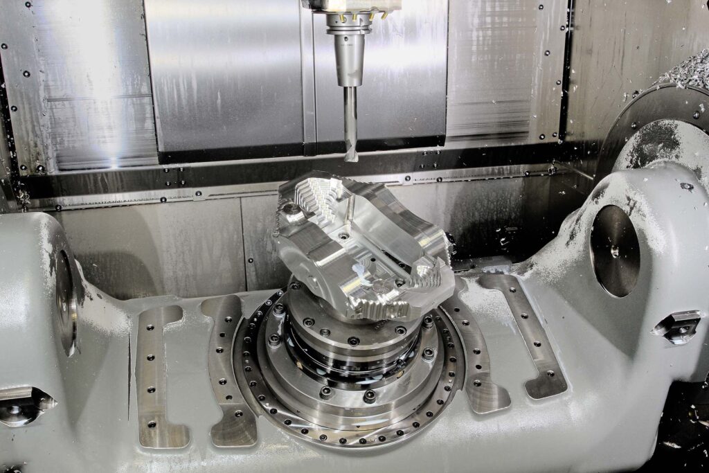
The part to be manufactured on CNC mill needs to be designed on and CAM software firstly. CAM is software that creates G-codes which define the tool’s path. These codes can be understandable to the CNCs. The tools path is simulated before creating the G-codes file if there are no accidents and tool interferences with the functional area of the part. The frequently used GUI software are Power Mill, Solid CAM, Fusion 360, CATIA, and PTC Creo. While designing a model in CAD to milling on CNC, a few things need to remember.
- CNC mill uses high RPM tools; if the CAD model has a thin wall due to shear stresses, it can break or tilt. So, in CAD modeling, thin walls avoidance should be observed. The minimum thickness for metals is 0.75mm and for plastic is 1.5 to 2.0mm.
- The depth should not exceed three or four times the end mill tool.
- The diameter of the tool needs to be taken into account while calculating internal corners. For example, T-Bone is a tool with T –Shape. While making a 3D model, the major diameter of the tool needs observance for the depth of the corners.
- Holes that require tight tolerance should be designed in the CAD model without giving tolerance.
- Designing threads in a model in CAD, M6, and larger sizes should be kept.
- Geometries like curved holes should be avoided because tools cannot mill/bore these geometries.
- In the case of designing mold on CAD (core and cavity), the final product needs to be observed if it is easily removable.
- High depth to width ratio causes the tool to hang, deflect and chip evacuation and fracture of the tool. So, considering depth to width ratio should be taken into account.
- Radii, according to the end mill, tool diameter should be designed in CAD for internal corners because the mill is unable to mill sharp corners more than the minimum tool diameter.
- The final geometry should be checked if there is not happening any tool accident in CAM software. This feature is available in all CAM versions.
- CNCs have a specific length of tools, so the part should be designed in such a manner that tools have access thoroughly.
Optimize Designs for CNC Milling
- In engineering practice, observation says that the first few threads are responsible for stress-bearing, so, in the CAD model, long threads design may be avoided.
- A larger block size means more time for machining. Block size should be small as possible.
- Aesthetic features, which influence the product’s main function should be avoided.
- Feature with two minor functions which may be neglected.
- Standard sizes for holes and threads need to be used.
- Lead-time is always a concern in the manufacturing industries, which can be reduced by avoiding unnecessary machining of the part.
- The machinability of the material should be taken into account because the physical properties of the material play an important role. Material with high machinability will reduce the lead-time.
- Space between texts on the part should be according to the tools so that changing of tools does not occur.
- Anodes are inserting parts to machined mold, which are changing in every batch. The use of anodes may be taken into account for such production. It avoids mold redesign for every batch.
- Split up complex and simple parts. The simple and complex should be milled separately because milling combined will increase the lead-time.
- Each design has its requirements for the surface finish; the surface finish should be done accordingly. Multiple surface finish exceeding the design requirement will cost while adding no value to the final product.
Eliminate Overlapping Geometry
Geometries that intersect at one or more features but not all. These geometries are a design concern because the manufacturing of these parts may be impossible in practice. To avoid intersecting/overlapping geometries, the following measure may be taken:
- In 3-axis milling, these geometries should be completely avoided because tools cannot be able to access these locations.
- While in the case of 5-axis and 9-axis milling, the tool length, diameter, and the angle at which tools can be set should be taken into account if the location is accessible from that angle and length.
Conclusion
The first step of CNC milling is the CAD model, which needs to be designed carefully. Designing CAD for CNC should avoid thin walls, unnecessary depth of the holes, and threads (high depth to width ratio), unnecessary machining, complex and small text on the part, and unfeasible geometries like curved holes inaccessible features. A good CNC CAD model must possess round corners internally, and tools access to the whole part.
Optimal design can simplify the model by which parts are necessary and which are not. Optimized design should avoid aesthetic features if not required, features with too minor function which may be neglected, and unnecessary machining. Optimal design should account for stress-taking threads, which are the first few threads, use standard sizes for holes, machinability of the materials and threads, and reduce lead time.
Overlapping geometries should be avoided in 3-axis milling. In the case of 5-axis milling and 9-axis milling, the tool’s length, diameter, and the angle at which the tool can be set should be taken into account if the location is accessible easily to be milled.


